

Product Video
Product Description

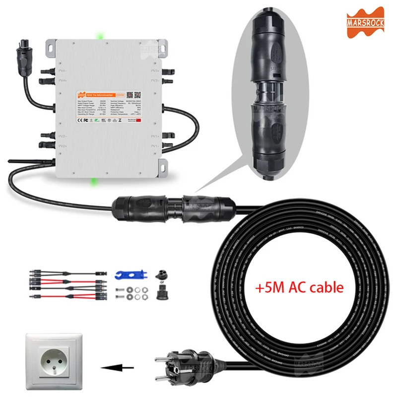
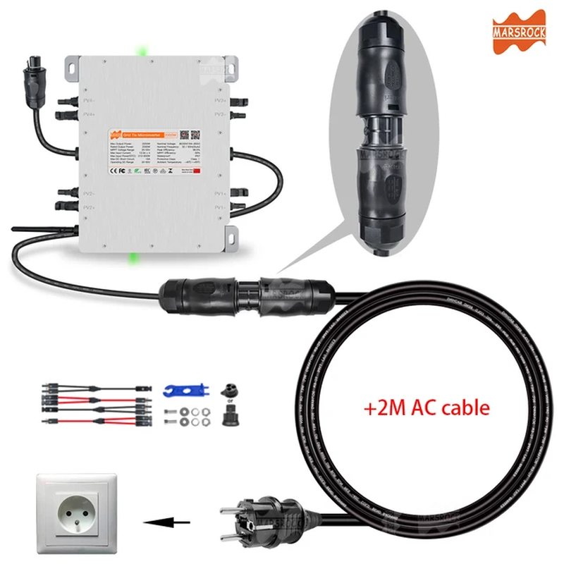
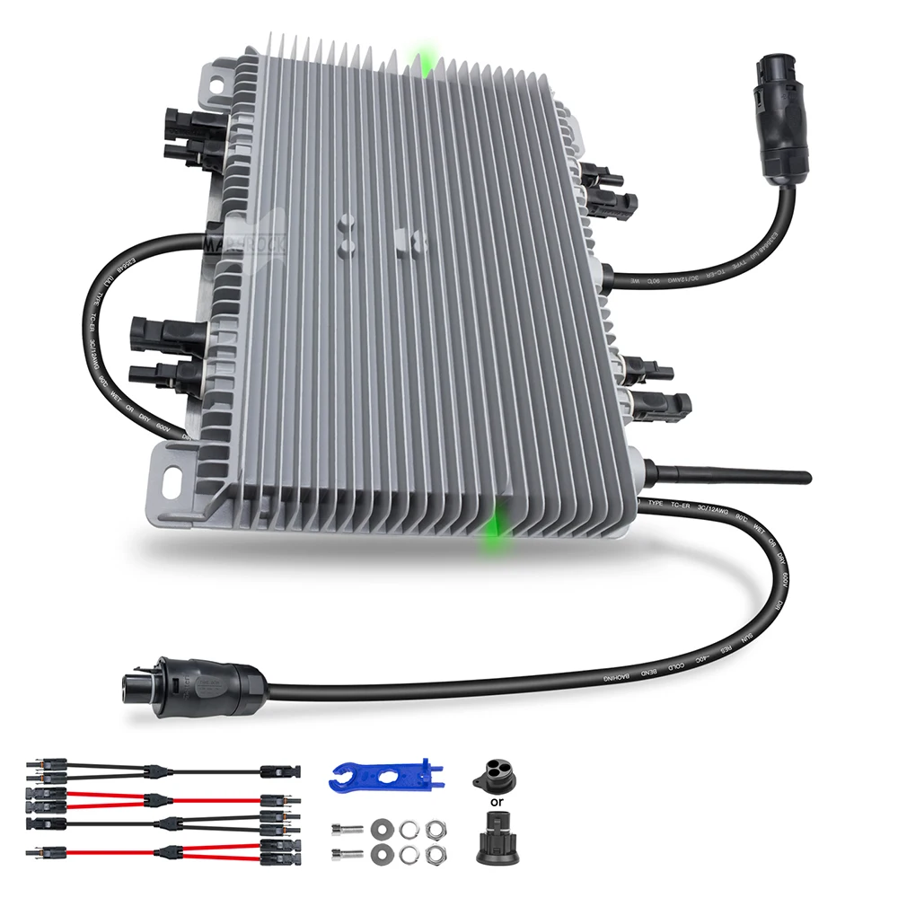
*Attention!! You can click the below Cord picture to buy this high quality AC Power Extension
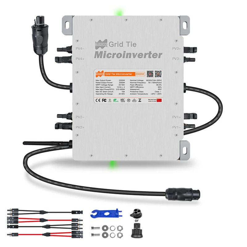
Product Introduction.
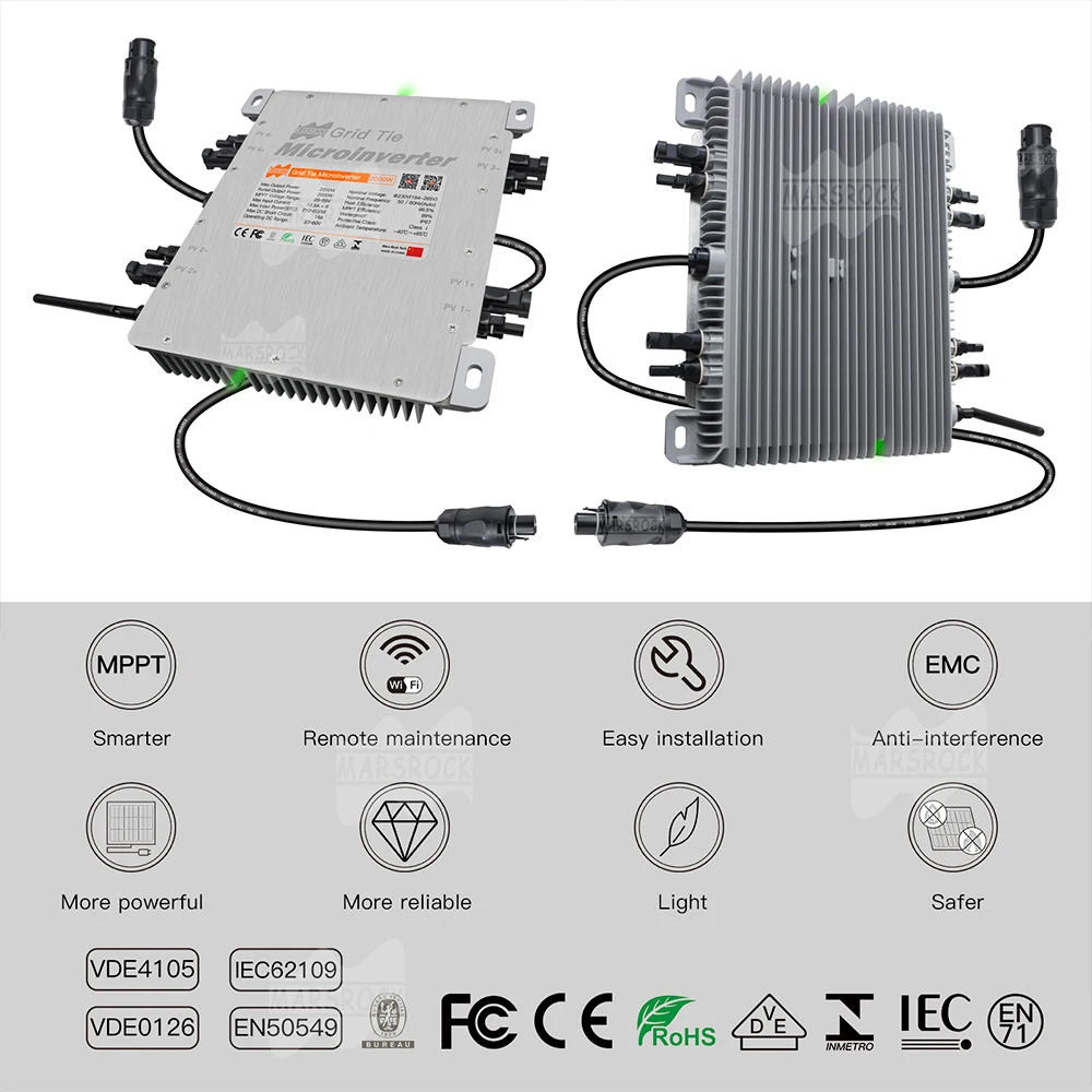
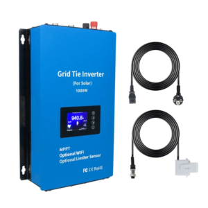
* Rapid shutdown function
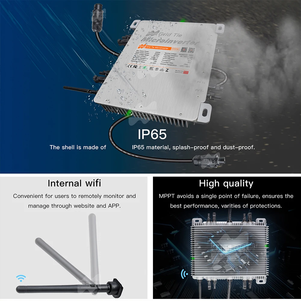
* IP67 protection degree, 10 years warranty
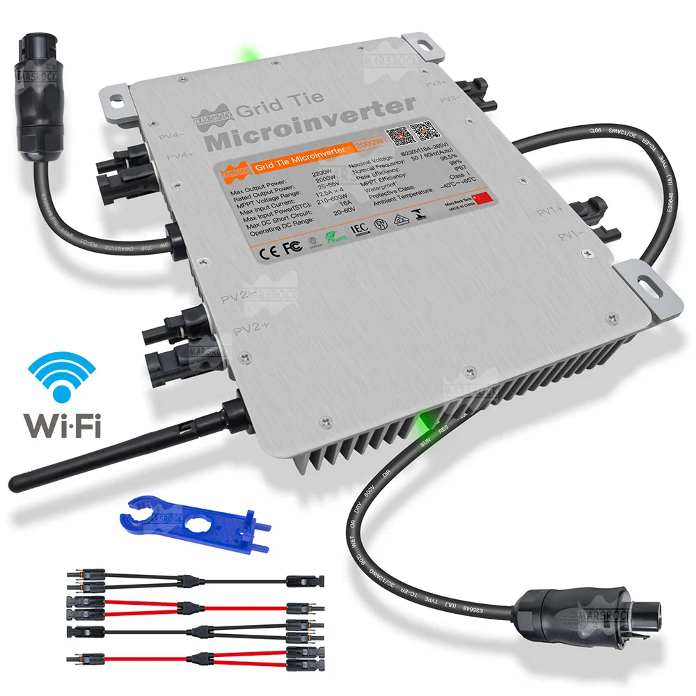
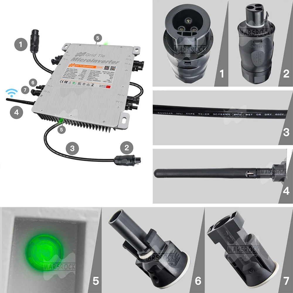
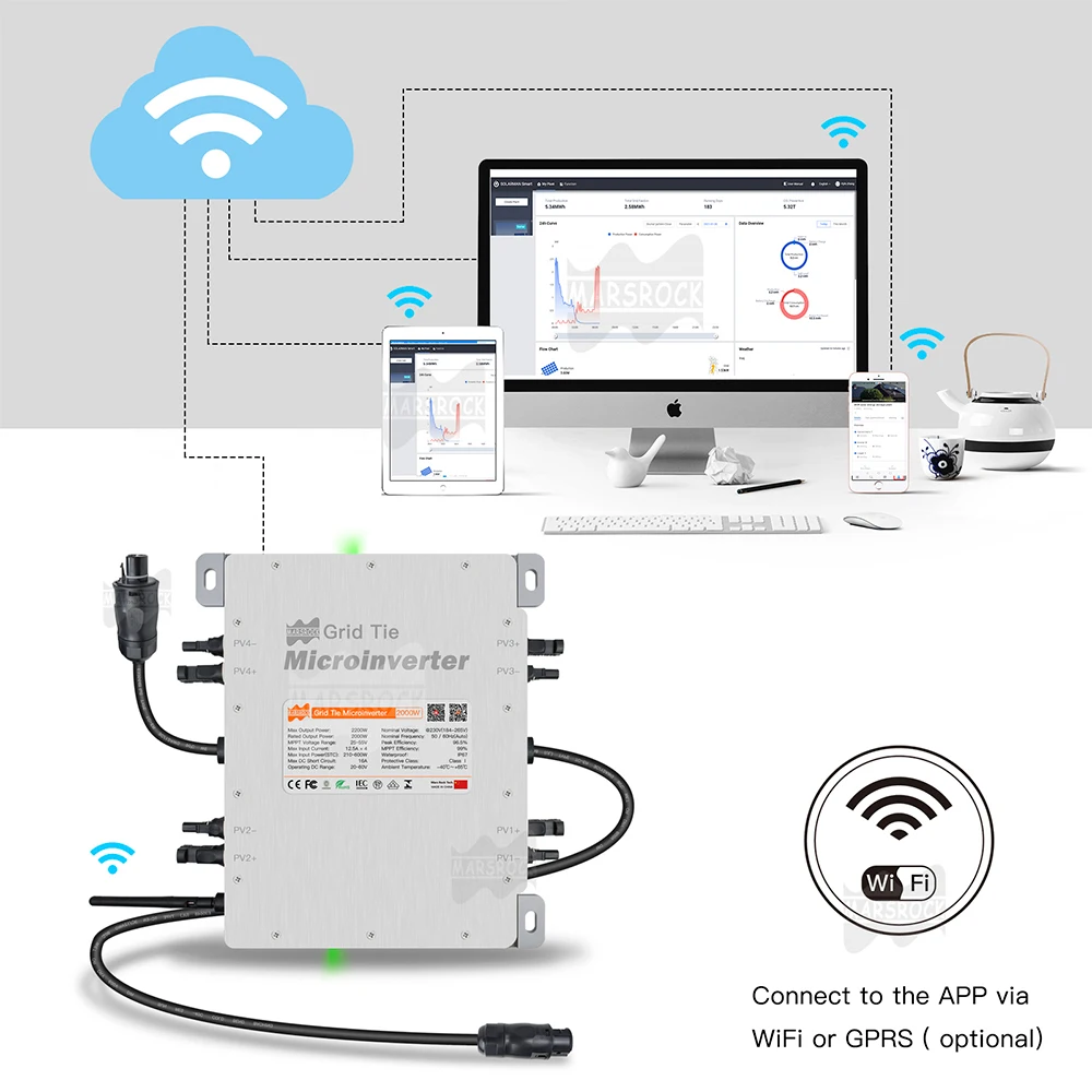
* PLC, Zigbee or WIFI communication
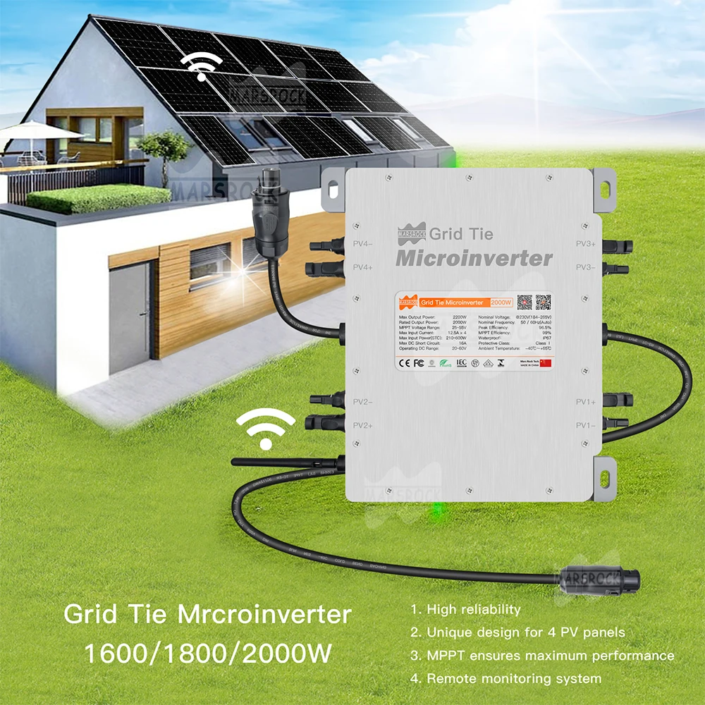
* 4 MPP trackers, module level monitoring
* Max. DC input current of 12.5A, adapt to 600W PV module
Microinverter System Introduction
The Microinverter is used in utility-interactive grid-tied applications, comprised of two key elements:
* Microinverter
* Router
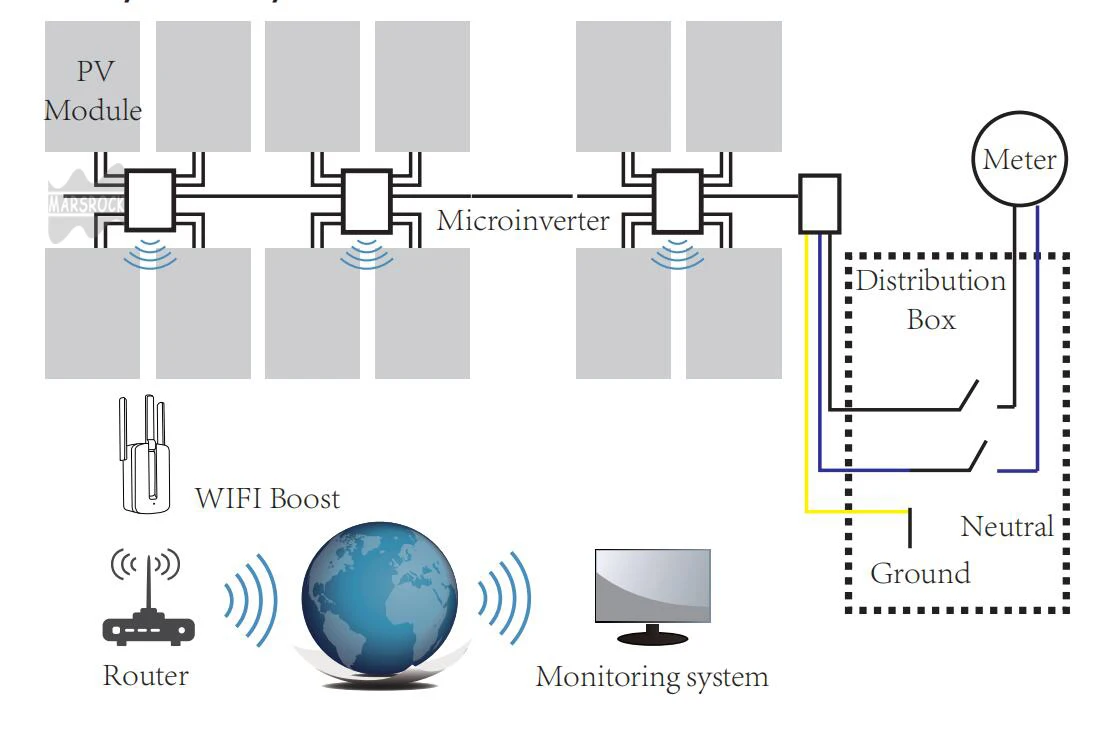
Note:If the wireless signal in the area where the microinverter is weak, it is necessary to add a wifi signal booster at a suitable place between the router and the microinverter.
This integrated system improves safety; maximizes solar energy harvest;increases system reliability, and simplifies solar system design, installation,maintenance, and management.
Microinverters Maximize PV Energy Production:
Each PV module has individual Maximum Peak Power Tracking (MPPT) controls, which ensures that the maximum power is exported to the utility grid regardless of the performance of the other PV modules in the array.When PV modules in the array are affected by shade, dust, orientation,or any situation in which one module underperforms compared with the other units, the Microinverter ensures top performance from the array by maximizing the performance of each module within the array.
More Reliable than Centralized or String Inverters:
The distributed Microinverter system ensures that no single point of system failure exists across the PV system.Microinverters are designed to operate at full power at ambient outdoor temperatures of up to 149℉ (65℃). The inverter housing is designed for outdoor installation and complies with the IP65 environmental enclosure rating.
Simple to Install:
You can install individual PV modules in any combination of Module quantity, orientation, different type and power rate The Ground wire (PE) of the AC cable is connected to the chassis inside of the Microinverter,potentially eliminating the installation of grounding wire (check local regulation). Data collection adopts internal wifi,wireless router is needed near the microinverter. When complete the installation of microinverter,configure wireless router with internal wifi(refer to the wifi user manual).The data will be uploaded automatically.Users can monitor and manage the microinverter through corresponding website or APP.
Microinverter Introduction:
The Microinverters connect with the single-phase grid, and can also use multiple Micro inverters in the form of single-phase grid to achieve three-phase grid.
Product Paramenters
|
Model |
2000W |
|
Input Data |
|
|
Max solar panel |
4*600W (max) |
|
Start-Stop voltage |
20-60V |
|
Reccommend PV Voc |
33-60V |
|
MPPT |
25-55V |
|
Max Input Current |
12.5A*4 |
|
DC short current |
16A*4 |
|
Output Data |
|
|
Rated Output Power |
2000W |
|
Max output Power |
2112W |
|
Rated output current |
@230VAC 9.2A |
|
Rated voltage |
@230V(184-265VAC) |
|
Max units per branch |
@230V:4PCS |
|
Rrequency |
50/60Hz(45~65Hz) |
|
Output Efficiency |
|
|
Static MPPT |
99.00% |
|
CEC Weighted Efficiency |
95% |
|
Max output |
96.5% |
|
Self consumption |
50mW |
|
THD |
<3% |
|
Exterior |
|
|
Ambient temperature |
– 40℃ to +80℃ |
|
Operating temperature |
– 40℃to +65℃ |
|
Dimensions(L×W×H) |
267×300×42.5 mm (Without mounting bracket and cable) |
|
Net Weight(KGS) |
5.3 |
|
Waterproof Rating |
IP67 |
|
Cooling |
Self-cooling |
|
Feature |
|
|
Compatibility |
Compatible with 60~72 cell PV modules |
|
Communication |
Power line / WIFI/Zigbee |
|
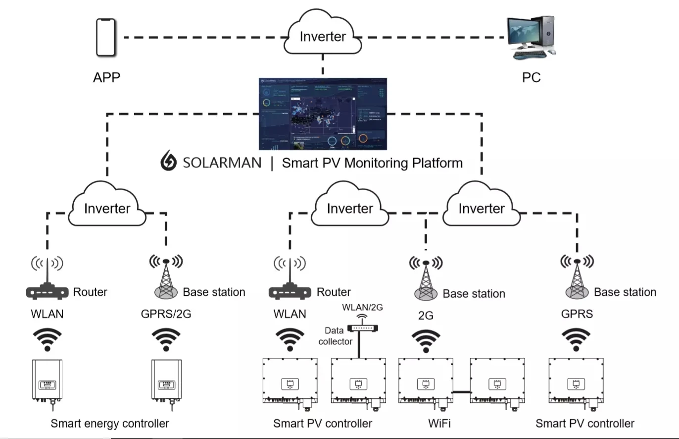
Monitoring System |
Lifetime free |
|
Electromagnetic compatibility |
EN50081.part1EN50082.part1 |
|
Grid disturbance |
EN61000-3-2 Safety EN62109 |
|
Grid detection |
DIN VDE 1026 UL1741 |
|
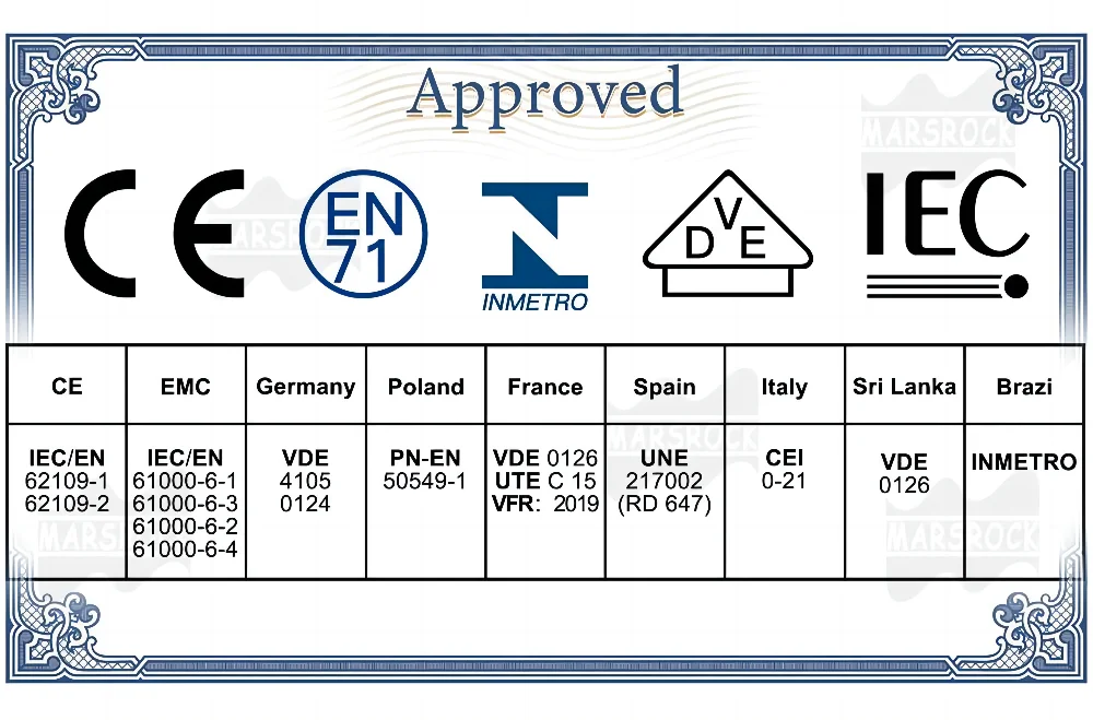
Certificate |
UL1741、VDE0126、VDE4105、IEC62109、CE、INMETRO |
Details Images


Installation Instructions
Installation Procedures
Microinverter System Installation:
A PV system using Microinverters is simple to install. Each Microinverter easily mounts on the PV racking, directly beneath the PV module(s). Low voltage DC wires connect from the PV module directly to the Microinverter, eliminating the risk of high DC voltage.Installation MUST comply with local regulations and technical rules. Special Statement! An AC GFCI device should not be used to protect the dedicated circuit
to the microinverter even though it is an outside circuit. None of the small GFCI devices (5~30mA) are designed for back feeding and will be damaged if back feed. In a similar manner, AC AFCIs have not been evaluated for back feeding and may be damaged if back feed with the output of a PV inverter.
WARNING:Perform all electrical installations in accordance with local electrical codes.
WARNING:Be aware that only qualified professionals should install and/or replace Microinverters.
WARNING:Before installing or using an Microinverter,please read all instructions and warnings in the technical documents and on the Microinverter system itself as well as on the PV array.
WARNING:Be aware that installation of this equipment includes the risk of electric shock.
WARNING:Do not touch any live parts in the system, including the PV array, when the system has been connected to the electrical grid.
NOTE:Strongly recommend to install Surge protection Devices in the dedicated meter box.
Step 1- Install the AC branch circuit junction box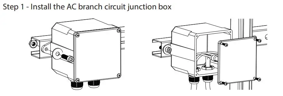
a. Install an appropriate junction box at a suitable location on the PV racking system
(typically at the end of a branch of modules).
b. Connect the open wire end of the AC cable into the junction box using an appropriate gland or strain relief fitting.
c. Wire the conductors of the AC(230/400Vac): L – red; N – black ;PE – yellow green.
d. Connect the AC branch circuit junction box to the point of utility Interconnection.
WARNING: Wiring colour code can be diferent according local regulation, check all the wires of the installaton before connecting to the AC cable to be sure they match. Wrong cabling can damage ireparably the mroinertersush an issue is not covered by the warranty.
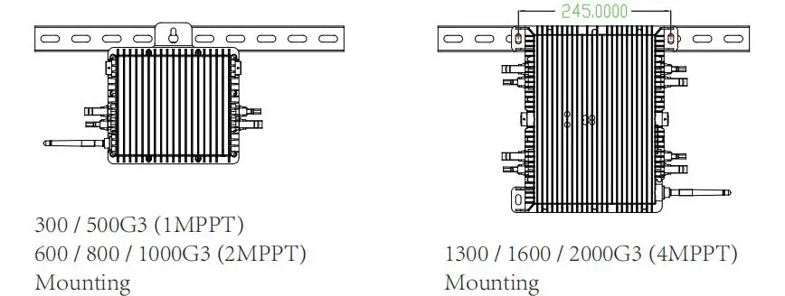
Step 2- Attach the Microinverters to the racking or the PV module frame
a. Mark the location of the Microinverter on the rack, with respect to the PV module junction box or any other obstructions.
b. Mount one Microinverter at each of these locations using hardware recommended by your module racking vendor.
WARNING: Prior to installing any of the microinverters, verify that the utility voltage at the point of common connection matches the voltage rating on microinverter label.
WARNING: Do not place the inverters (including DC and AC connectors) where exposed to the sun, rain or snow, even gap between modules.Allow a minimum of 3/4 (1.5cm.) between the roof and the bottom of the Microinverter to allow proper air flow.
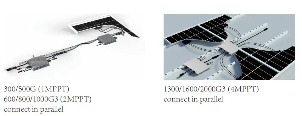
Step 3 – Connect the microinverters in parallel
a. Check the Microinverter technical data page 5 for the maximum allowable number of Microinverters on each AC branch circuit.
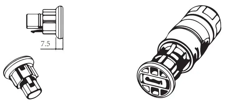
b. Plug the male AC connector of the Microinverter into the female connector to get it connected.AC connector interface as follows.
WARNING: DO NOT exceed maximum number of Microinverters in an AC branch circuit, as displayed on the page 5 of this manual.

Step 4- Install an AC cable protective end cap at the end of AC cable
Step 5 – Connect Microinverter to the PV Modules

Note:When plugging in the DC cables, if AC already available,the Microinverter should immediately blink red light and will start work within the setting time (default 60 seconds). If AC is not available,the red light will blink 3 times quickly and repeat after one second until AC is connected.
Microinverter System Operating Instructions
To operate the microinverter PV system:
1. Turn ON the AC circuit breaker on each microinverter AC branch circuit.
2. Turn ON the main utility-grid AC circuit breaker. Your system will start producing power after a one-minute waiting time.
3. The units should start blinking red one minutes after turning on the AC circuit breaker. Then blue led blinking. This means they are producing power normally, the faster blinking of the blue led means more power generated.
4. Configure the internal wifi module according to its user manual.
5. The Microinverters will start to send performance data over wifi module to the network every 5 minutes.It enables customers to monitor performance data of each microinverter through website and APP.
NOTE: When AC power is applied but the microinverter not started up, about 0.1A current and 25VA(W) power for each microinverter may be measured by a power meter. This power is reactive power,not consume from utility grid.
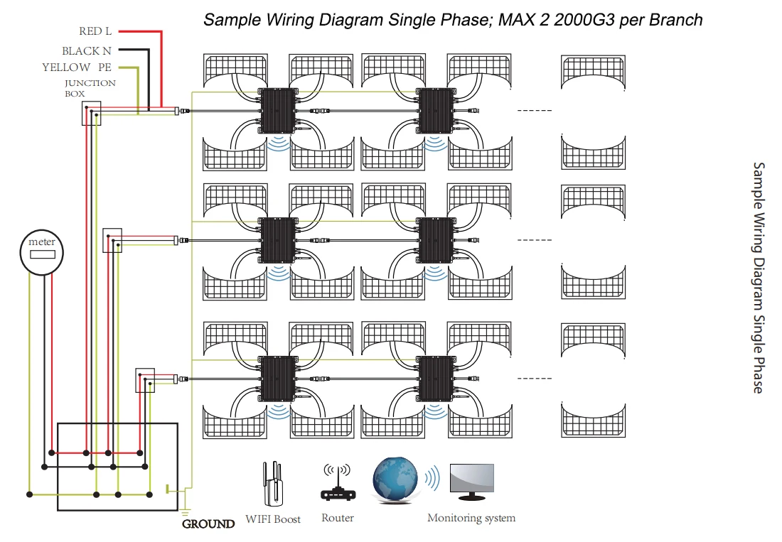
Sample Wiring Diagram Single Phase; MAX 22000G3 per Branch.
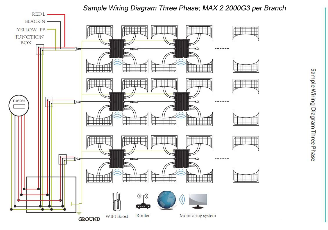
Sample Wiring Diapram Three Phase; MAX 22000G3 per Branch.

Factory Production Line Shows


Reviews
There are no reviews yet.